介绍
学习完Games101 一段时间后,发现自己对一些基础知识掌握得不够牢固,就从零手搓了一个软光栅渲染器。
目标是过一遍光栅化渲染管线,所以不考虑算法优化,以及例如图片解码读取这些细分内容。
用glfw实现窗口创建和像素点绘制,基础的数学库和TGA图片读取类改写自TinyRenderer 教程提供的数学库,其余实现流程全是自己手搓的。
项目地址:https://github.com/himoqiuhan/QiuHRenderer
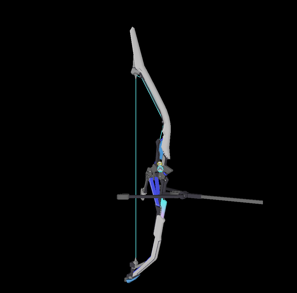
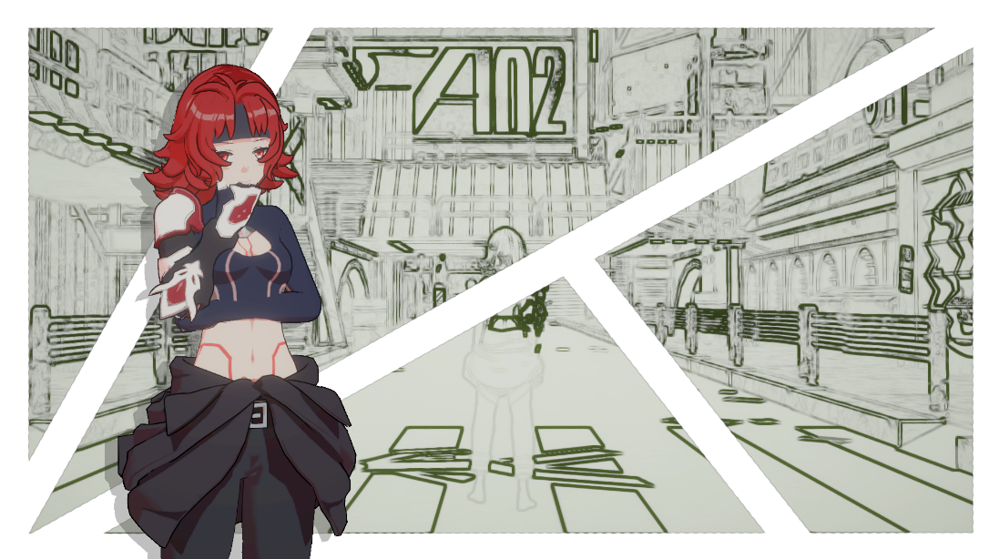
部分效果图:
贴图读取与映射
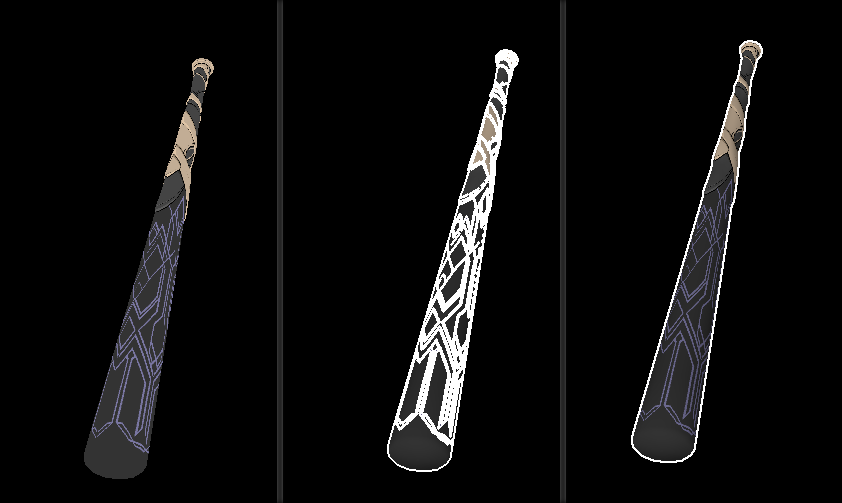
“伪后处理”描边效果
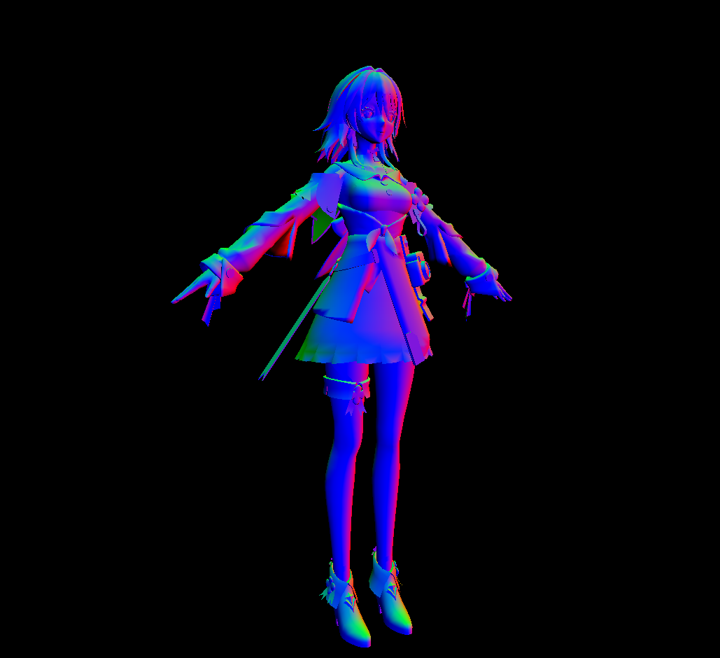
平滑法线
深度图渲染
渲染器整体架构
传入模型、读取光照信息
-–for(每个面)
定义v2f结构体数组vertexout[3]
–for(3个顶点)
GetVertexData获取当前顶点appdate_base顶点信息(顶点位置、顶点UV、顶点法线)
VertexShader给v2f赋值(裁剪空间坐标、世界空间坐标、世界空间法线、顶点UV)
透视除法->齐次裁剪空间:简单粗暴的放弃这个面片 continue!(因为写渲染器的目标在于捋清楚渲染流水线,所以不做深挖)
屏幕映射->屏幕空间:三角形设置(基于三角形GetAABB获取BoudingBox)
–for(BoundingBox)三角形遍历
IsInTriangle叉乘判断片元是否在三角形内
-if(在三角形内部)
GetBarycentric获取屏幕上的重心坐标
插值计算出该片元在candidate cube 中的z值->获取candidate cube 中的坐标
齐次裁剪空间的坐标转换到相机空间中
利用透视除法系数,反推出裁剪空间中的深度值fragDepth
判断fragDepth与zbuffer内的深度值
if(fragDepth.abs < zbuffer[])
写入当前深度值
FragmentShader输出片元颜色color4
DrawPixel
else
-else
细节分析
类、结构体的设计
Rasterizer类
实际的每一帧的渲染是在Rasterizer类中实现的,其中包含渲染前对模型变换、摄像机的设置,以及对渲染流程的执行
class Rasterizer { private : Transform transform; Camera camera; Screen screen; Matrix Matrix_M; Matrix Matrix_V; Matrix Matrix_P; Matrix Matrix_MVP; Vec3f worldLightDir; TGAImage* diffuseTex; std::vector<float > ZBuffer; std::vector<color4> FrameBuffer; std::vector<float > LuminanceBuffer; int fragCounter = 0 ; public : Rasterizer (const Screen& screen); ~Rasterizer (); void SetTransform (Vec3f transition, Vec3f rotation, Vec3f scale) void SetPerspective () void SetOrthogonal () void SetCamera (Vec3f _position, Vec3f _lookAt, Vec3f _lookUp, float _FOV, float _aspect, float _near, float _far) void SetCamera (Vec3f _position, Vec3f _lookAt, Vec3f _lookUp) void SetCamera (Vec3f _position) void ExeRenderPipeline (Model* model, TGAImage* diffuse, Vec3f light_dir) appdata_base GetVertexData (Model* model, Vec3i faceIndex) ; v2f VertexShader (appdata_base v) ; bool canClip (Vec3f* homogeneousPos) Vec3f ScreenMapping (Vec3f screen_coord) ; bool IsInTriangle (Vec2i frag, Vec3f* triangleVertex) float GetFragHomogeneousDepth (float * triangleVertexDepths, Vec3f barycoord) float GetFragW (float * triangleVertexW, Vec3f barycoord) color4 FragmentShader (v2f* i, float fragW, Vec3f barycoord) ; Vec3f ObjectToWorldNormal (Vec3f normal) ; Vec3f GetFragNormalByVertNormal (Vec3f* triangleVertexNormals, Vec3f barycoord) ; void DrawFrag (Vec2f pos, color4 color) };
基础信息结构体
屏幕/窗口信息
用于存储所创建窗口的长、宽信息
struct Screen { int width = 640 ; int height = 480 ; Screen () {}; Screen (int w, int h) :width (w), height (h) {}; };
变换信息
用于存放物体在世界空间下的变换(平移、旋转和缩放),其中由于后续在矩阵设置过程中进行了角度值到弧度值的转换,所以这里的旋转所用的是角度值
struct Transform { Vec3f transition = Vec3f (0 , 0 , 0 ); Vec3f rotate = Vec3f (0 , 0 , 0 ); Vec3f scale = Vec3f (1 , 1 , 1 ); void SetTransform (Vec3f _transition, Vec3f _rotation, Vec3f _scale) { transition = _transition; rotate = _rotation; scale = _scale; } };
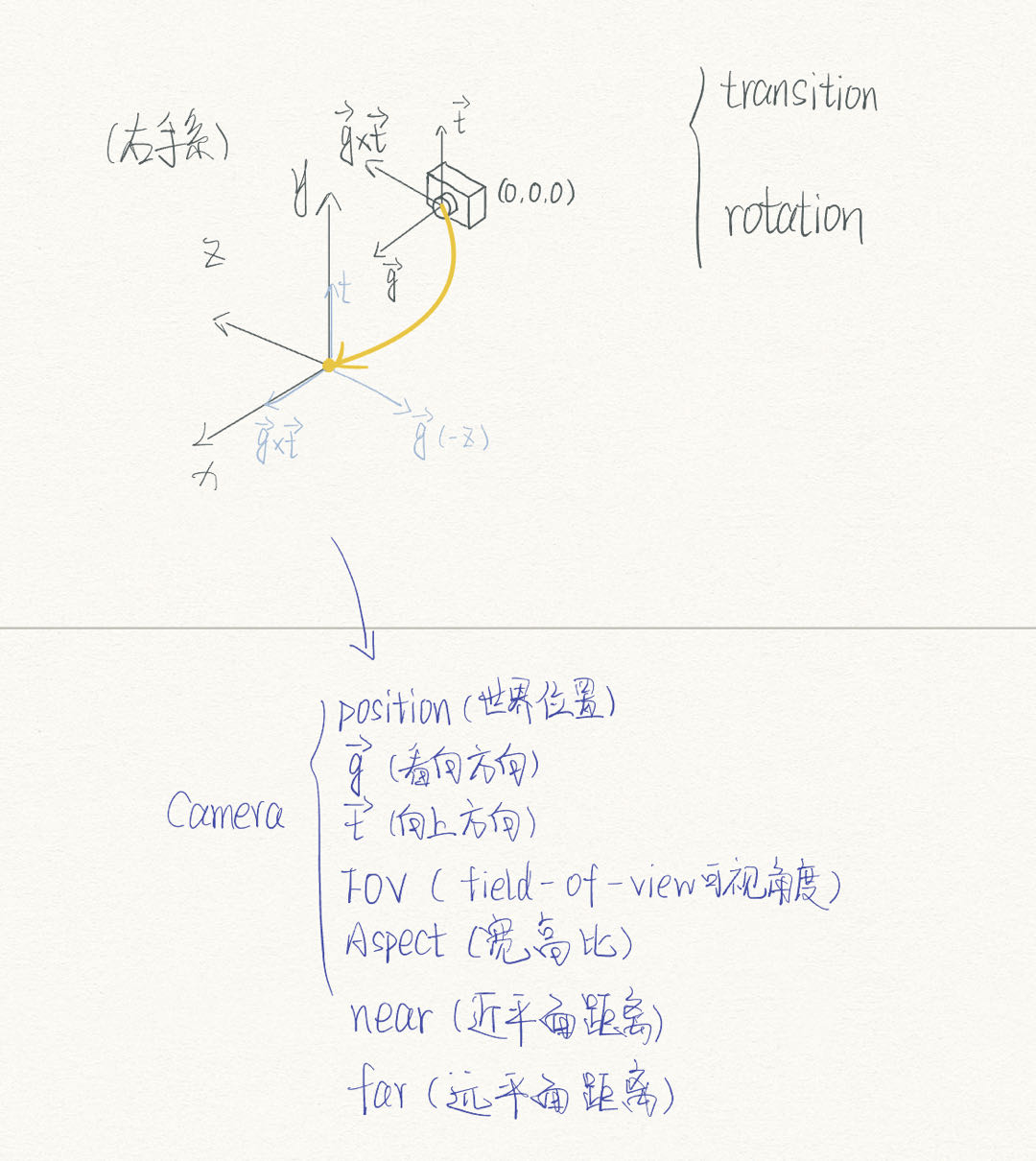
相机信息
有关信息见如下注释
struct Camera { Vec3f position = Vec3f (0 , 0 , 0 ); Vec3f g = Vec3f (0 , 0 , -1 ); Vec3f t = Vec3f (0 , 1 , 0 ); float FOV = 60 ; float aspect = 16 / (float )9 ; float near = 0.1f ; float far = 100.f ; };
颜色信息
用于对颜色的RGBA值进行存储,加入一些简单的相加、相乘和增加对比度的功能
struct color4 { float r; float g; float b; float a; color4 () : r (1 ), g (1 ), b (1 ), a (1 ) {}; color4 (float R, float G, float B, float A) : r (R), g (G), b (B), a (A) {} color4 operator *(float num) { return color4 (r * num, g * num, b * num, a * num); } color4 operator *(color4 other) { return color4 (r * other.r, g * other.g, b * other.b, a * other.a); } color4 operator +(color4 other) { return color4 (r + other.r, g + other.g, b + other.b, a + other.a); } color4 AddContrast (float power) { return color4 (std::pow (r, power), std::pow (g, power), std::pow (b, power), 1.f ); } };
信息传递结构体
appdate_base
用于将模型信息传输给顶点着色器
struct appdata_base { Vec3f vertex; Vec3f normal; Vec2f texcoord; };
v2f
用于将顶点着色器传出的数据发送给片元着色器
struct v2f { Vec4f clipPos; Vec3f worldPos; Vec3f worldNromal; Vec2f uv; };
矩阵变换
矩阵相关的内容在/scr/Support/Math中的Matrx.cpp中,只做了更常用的透视投影,没有做正交投影的矩阵变换
Model Matrix
将顶点数据从Model Space变换到World Space,处理顶点数据的平移、旋转和缩放
此处使用的变换顺序是旋转-缩放-平移,其中旋转传入的是角度值的数值,在内部进行了角度值到弧度制的转换
Matrix GetModelMatrix (const Transform& transform) Vec3f rotateRadian (transform.rotate.x * 3.14f / 180 , transform.rotate.y * 3.14f / 180 , transform.rotate.z * 3.14f / 180 ) ; return GetTransition (transform.transition) * GetScale (transform.scale) * GetRotation (rotateRadian); }
View Matrix
将顶点数据从World Space变换到View Space中,处理摄像机的变换,获得顶点数据在View Space下的坐标信息,确定View Space时使用的是右手系
Matrix GetViewMatrix (const Camera& camera) Matrix t = mat<4 , 4 , float >::identity (); t[0 ][3 ] = -camera.position.x; t[1 ][3 ] = -camera.position.y; t[2 ][3 ] = -camera.position.z; Vec3f gxt = cross (camera.g, camera.t); Matrix r; r[0 ][0 ] = gxt.x; r[0 ][1 ] = gxt.y; r[0 ][2 ] = gxt.z; r[1 ][0 ] = camera.t.x; r[1 ][1 ] = camera.t.y; r[1 ][2 ] = camera.t.z; r[2 ][0 ] = -camera.g.x; r[2 ][1 ] = -camera.g.y; r[2 ][2 ] = -camera.g.z; r[3 ][3 ] = 1 ; return r * t; }
Perspective Matrix
将顶点数据从View Space变换到Clip Space裁剪空间中,待后续进行透视除法变换到齐次裁剪空间进行裁剪和屏幕映射
Matrix GetPerspectiveMatrix (const Camera& camera) float cot = 1.0f / std::tan ((camera.FOV / 2.0f ) * 3.14f / 180 ); Matrix ret; ret[0 ][0 ] = cot / camera.aspect; ret[1 ][1 ] = cot; ret[2 ][2 ] = -(camera.far + camera.near) / (camera.far - camera.near); ret[2 ][3 ] = -2 * camera.far * camera.near / (camera.far - camera.near); ret[3 ][2 ] = -1 ; return ret; }
渲染流程
Rasterizer类中的成员函数ExeRenderPipeline,流程和渲染器架构 部分的内容基本相同,只是项目源文件中放了很多用于deBug的宏定义,所以在此留一个纯净版
void Rasterizer::ExeRenderPipeline (Model* model, TGAImage* diffuse, Vec3f light_dir) worldLightDir = light_dir * -1.f ; this ->diffuseTex = diffuse; std::cout << std::endl; std::cout << "|||||||||||||||||||ExeRenderPipeline 单帧开始|||||||||||||||||||" << std::endl; std::cout << "||||||||||||||||摄像机基本信息: " << "position: " << camera.position << " LookAt: " << camera.g << " LookUp: " << camera.t << std::endl; std::cout << "||||||||||||||||光照方向:" << worldLightDir << std::endl; for (int i = 0 ; i < model->nfaces (); i++) { v2f vertexout[3 ]; std::vector<Vec3i> face = model->face (i); for (int j = 0 ; j < 3 ; j++) { appdata_base VertexData = GetVertexData (model, face[j]); vertexout[j] = VertexShader (VertexData); } float w[3 ]; Vec3f homogeneousClipPos[3 ]; for (int j = 0 ; j < 3 ; j++) { w[j] = vertexout[j].clipPos.w; homogeneousClipPos[j] = (vertexout[j].clipPos / w[j]).xyz (); } if (canClip (homogeneousClipPos)) continue ; Vec3f screen_coords[3 ] = { ScreenMapping (homogeneousClipPos[0 ]), ScreenMapping (homogeneousClipPos[1 ]), ScreenMapping (homogeneousClipPos[2 ]) }; std::tuple<Vec2i,Vec2i> bbox = GetBoudingBox (screen_coords); for (int y = std::get <0 >(bbox).y; y <= std::get <1 >(bbox).y; y++) { for (int x = std::get <0 >(bbox).x; x <= std::get <1 >(bbox).x; x++) { if (!IsInTriangle (Vec2i (x, y), screen_coords)) continue ; Vec3f BarycentricCoordinate = GetBarycentricCoordinate (screen_coords, Vec2f (x+.5 , y+.5 )); float vertexDepth[3 ] = { screen_coords[0 ].z,screen_coords[1 ].z,screen_coords[2 ].z }; float homogeneousDepth = GetFragHomogeneousDepth (vertexDepth, BarycentricCoordinate); float fragW = GetFragW (w, BarycentricCoordinate); float depth = homogeneousDepth * fragW; if (std::abs (depth) < ZBuffer[y * screen.width + x]) { ZBuffer[y * screen.width + x] = depth; color4 FragColor = FragmentShader (vertexout, fragW, BarycentricCoordinate); fragCounter++; if (FragColor.r == -1 || FragColor.g == -1 || FragColor.b == -1 ) continue ; } } } } std::fill (ZBuffer.begin (), ZBuffer.end (), 99 ); std::fill (FrameBuffer.begin (), FrameBuffer.end (), color4 (0 ,0 ,0 ,0 )); std::fill (LuminanceBuffer.begin (), LuminanceBuffer.end (), 0 ); std::cout << "执行Fragment Shader 数量:" << fragCounter << std::endl; fragCounter = 0 ; std::cout << "|||||||||||||||||||ExeRenderPipeline 单帧结束|||||||||||||||||||" << std::endl; std::cout << std::endl; }
额外内容
Frame Buffer
最简易的版本将是直接将当前渲染到的像素直接绘制到屏幕上,后续加入了Frame Buffer,渲染器会先将颜色数据存储到Frame Buffer中,经过处理后再绘制到屏幕。
使用时直接在上方宏定义处定义#define DEFERREDRENDERING_ON即可
				if (std::abs(depth) < ZBuffer[y * screen.width + x])
				{
					ZBuffer[y * screen.width + x] = depth;
					color4 FragColor = FragmentShader(vertexout, fragW, BarycentricCoordinate);

					fragCounter++;

					if (FragColor.r == -1 || FragColor.g == -1 || FragColor.b == -1) continue;

- 					DrawFrag(Vec2f(x + .5, y + .5), FragColor);
+					FrameBuffer[y * screen.width + x] = FragColor;//写入FrameBuffer

//...
//...

+	for (int y = 0; y < screen.height; y++)
+	{
+		for (int x = 0; x < screen.width; x++)
+		{
+			DrawFrag(Vec2f(x + .5, y + .5), FrameBuffer[y * screen.width + x]);
+		}
+	}
渲染深度图
简单的渲染ZBuffer中的信息,在这个渲染器中,我想做出Deferred Render的感觉,所以实现需要#define DEFERREDRENDERING_ON来实现
只是将绘制Frame Buffer替换成了绘制ZBuffer
	for (int y = 0; y < screen.height; y++)
	{
		for (int x = 0; x < screen.width; x++)
		{
-			DrawFrag(Vec2f(x + .5, y + .5), FrameBuffer[y * screen.width + x]);
+			DrawFrag(Vec2f(x + .5, y + .5), color4(ZBuffer[y * screen.width + x] / 120, ZBuffer[y * screen.width + x] / 120, ZBuffer[y * screen.width + x] / 120, 1.f).AddContrast(.5));
		}
	}
得到亮度图
亮度计算方法:L u m i n a n c e = r ∗ 0.2125 + g ∗ 0.7154 + b ∗ 0.0721 Luminance = r * 0.2125 + g * 0.7154 + b * 0.0721 Lu minan ce = r ∗ 0.2125 + g ∗ 0.7154 + b ∗ 0.0721
if (std::abs(depth) < ZBuffer[y * screen.width + x])
{
	ZBuffer[y * screen.width + x] = depth;
	color4 FragColor = FragmentShader(vertexout, fragW, BarycentricCoordinate);
	fragCounter++;
	if (FragColor.r == -1 || FragColor.g == -1 || FragColor.b == -1) continue;
	FrameBuffer[y * screen.width + x] = FragColor;
+	LuminanceBuffer[y * screen.width + x] = FragColor.r * 0.2125 + FragColor.g * 0.7154 + FragColor.b * 0.0721;//写入亮度LuminanceBuffer
}
基于深度/亮度的简单描边效果
绘制Frame Buffer时,遍历每个像素并判断是否应该进行描边绘制
此处我使用当前像素周围八个像素,对角及上下左右的颜色信息差距,通过相减除以像素差来模拟颜色信息差的二阶导数,来判断是否描边
基于深度
if (y > 1 && y < screen.height - 1 && x > 1 && x < screen.width - 1 ){ if ((std::abs ((ZBuffer[(y + 1 ) * screen.width + x + 1 ] - ZBuffer[(y - 1 ) * screen.width + x - 1 ]))/(float )2.8 > .2f ) || (std::abs ((ZBuffer[(y - 1 ) * screen.width + x + 1 ] - ZBuffer[(y + 1 ) * screen.width + x - 1 ]))/(float )2.8 > .2f ) || (std::abs ((ZBuffer[y * screen.width + x + 1 ] - ZBuffer[y * screen.width + x - 1 ])) / (float )2 > .2f ) || (std::abs ((ZBuffer[(y + 1 ) * screen.width + x] - ZBuffer[(y - 1 ) * screen.width + x])) / (float )2 > .2f )) DrawFrag (Vec2f (x + .5 , y + .5 ), color4 (1 , 1 , 1 , 1 )); else DrawFrag (Vec2f (x + .5 , y + .5 ), FrameBuffer[y * screen.width + x]); } else DrawFrag (Vec2f (x + .5 , y + .5 ), FrameBuffer[y * screen.width + x]);
基于亮度
if (y > 1 && y < screen.height - 1 && x > 1 && x < screen.width - 1 ){ if ((std::abs ((LuminanceBuffer[(y + 1 ) * screen.width + x + 1 ] - LuminanceBuffer[(y - 1 ) * screen.width + x - 1 ]))/(float )2.8 > .05f ) || (std::abs ((LuminanceBuffer[(y - 1 ) * screen.width + x + 1 ] - LuminanceBuffer[(y + 1 ) * screen.width + x - 1 ]))/(float )2.8 > .05f ) || (std::abs ((LuminanceBuffer[y * screen.width + x + 1 ] - LuminanceBuffer[y * screen.width + x - 1 ]))/(float )2 > .05f ) || (std::abs ((LuminanceBuffer[(y + 1 ) * screen.width + x] - LuminanceBuffer[(y - 1 ) * screen.width + x]))/(float )2 > .05f )) DrawFrag (Vec2f (x + .5 , y + .5 ), color4 (1 , 1 , 1 , 1 )); else DrawFrag (Vec2f (x + .5 , y + .5 ), FrameBuffer[y * screen.width + x]); } else DrawFrag (Vec2f (x + .5 , y + .5 ), FrameBuffer[y * screen.width + x]);